



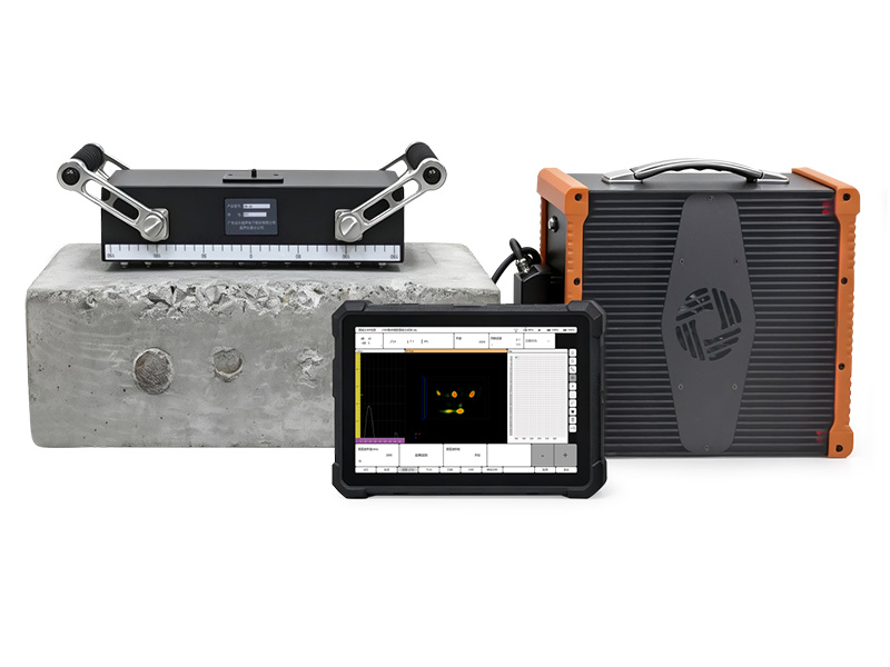


CTS-LPA70 Low-Frequency 3D Tomography TFM Phased-Array Instrument, it is a low-frequency phased array detector specially designed for inspecting high attenuation materials such as concrete and wind turbine blades.


CTS-LPA70 Low-Frequency 3D Tomography TFM Phased-Array Instrument, it is a low-frequency phased array detector specially designed for inspecting high attenuation materials such as concrete and wind turbine blades.
This intrument have parallel full matrix acquisition and multi modal TFM imaging, it supports flexible and adaptable for rectangular array transducers consisting of up to 64 shear wave Dry Point Contact (DPC) sensors, it can operate visual and real time three-dimensional imaging inspection for internal structures of high attenuation media including concrete, stone and refractory bricks, it accurately identify typical defects such as reinforcing bars, cables, voids, gaps, layers, cracks, fillers and inclusions. This product overcomes key core technologies in the field of concrete non destructive testing, its technical indicators have reached International advanced level, successfully resolved the choke point technical challenges and realises domestic substitution for high-end imported equipment.
Self-developed Dry Point Contact (DPC) Sensor:Equipped with wear-resistant ceramic sensing tips, it enables efficient acoustic wave transmission without couplant, greatly improving equipment durability and engineering applicability.
Single-sided Inspection:Only single-side contact with the concrete structure surface is required to complete 2D/3D imaging inspection, which significantly enhances inspection convenience and operability.
Adaptive Surface Coupling Mechanism:Integrated with an independent spring suspension structure, it automatically adjusts to rough and uneven concrete surfaces to guarantee stable inspection performance.
Shear Wave Excitation for High-resolution Inspection:An optimized acoustic excitation mechanism delivers shear-wave-dominated inspection, markedly boosting the resolution for tiny internal defects.
Real-time 3D Imaging System:Based on the DPC sensor array and total focusing method (TFM), it dynamically generates 3D tomographic images of the internal concrete structure.
Multi-dimensional Visual Analysis:Supports multi-plane slice views and 3D panoramic reconstruction images, providing multi-angle data support for defect localization and morphology interpretation.
Innovative Split Architecture Design:Adopts a split architecture for the main unit and array transducer. Via the IPEX phased-array interface, the main unit can flexibly match DPC sensor arrays, conventional phased-array probes and other types of array transducers.
CTS-LPA70主机性能指标:
| Basic Parameters | |
| Number of Channels | 32:64 channels (supports max 64-channel TFM) |
| Transmitter Parameters | |
| Pulse Mode | Bipolar square wave |
| Transmit Voltage | Up to ±200V |
| Pulse Width | 500ns ~ 50μs |
| Receiver Parameters | |
| Bandwidth | 20kHz ~ 2MHz (-3dB), multi-stage FIR filter supported |
| Sampling Frequency / Bit Depth | 20MHz / 14bit |
| Analog Gain Range | 0 ~ 70dB |
| Detection Capability | |
| Maximum Detection Depth | ≥0.8 m |
| Maximum Resolution | Rebar with diameter >10 mm, sphere of 20 mm detectable |
| Physical Parameters | |
| Data Communication | Wired Gigabit Ethernet / Wireless Wi-Fi |
| Power Supply | DC 13.5V / Battery 11.1V |
| Battery Endurance | ≥4 hours |
| Temperature Characteristics | Operating temperature: -10℃ ~ 45℃; Storage temperature: -20℃ ~ 60℃ |
| Main Unit Dimensions | 320mm×260mm×106mm (including frame rubber pad) |
| Main Unit Weight | 4.1 kg (excluding battery) |
| Software Functions | |
| Data Acquisition | 3D FMC data acquisition |
| Imaging Mode | 2D, 3D TFM imaging |
| Number of Focal Points | Up to 1,000,000 points |
| Image Frame Rate | 3D imaging > 1 Hz |
| Display Mode | A-Scan, B-Scan, C-Scan, 3D, 3D MAP |
| Analysis Software | Defect locating and quantitative measurement functions available |
CM-48阵列换能器性能指标:
| Receiver Parameters | |
| Quantity of Transducers | DPC × 48 |
| Nominal Frequency | 50 kHz Shear Wave |
| Preamplifier | Replaceable low-noise preamplifier module |
| Physical Parameters | |
| Dimensions | 320mm×150mm×90mm (including handle width) |
| Weight | 3.7 kg |
| Acquisition Mode | Auto / Manual |
| Auxiliary Positioning | Laser assisted positioning |
| Operation Method | Dual handles, multi-angle adjustable |
Case 1 | Inspection of Wind Turbine Hybrid Tower Segment Components
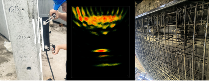
Segment inspection of hybrid tower — Imaging of dense reinforcing bars and φ12 mm voids
Single-sided inspection from the extrados of segment; clear discrimination of φ12 mm diameter voids, with simultaneous imaging of near-surface dense reinforcing bars.
Case 2|Wind Hybrid Tower Mock-up: Timber Strip Detected
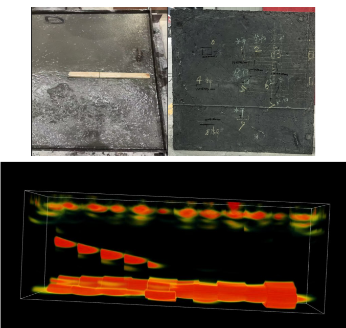
Imaging of mock-up specimen: rebars and timber strip (33×25×420 mm) are clearly distinguishable.
Grid-based 3D image stitching scan generates a full-view 3D MAP. Information such as the timber strip’s dimension, buried depth and orientation can be detected and analyzed, with well-separated imaging of rebars and timber strip.
Case 3 |Track Slab Void Model
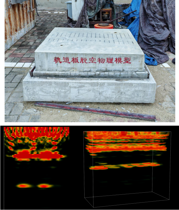
Track Slab Void Model Inspection — Rebars, Secondary Concrete Interface & Void Defects
Grid 3D stitching scan generates a full-view 3D MAP, visually presenting the internal rebar distribution and secondary concrete interface. Based on the strength of bottom-echo reflection signals, the void locations at the secondary concrete interface can be indirectly determined.
Track Lining Physical Model
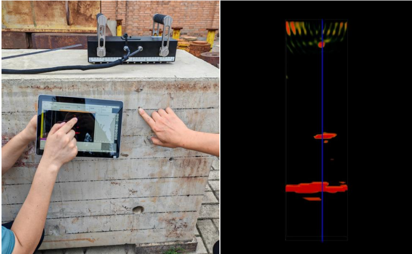
Lining Model: φ5 Rebar (buried 100 mm) & φ50 Void (buried 550 mm) Detected
Single-sided inspection performed from directly above the specimen: both the φ5 rebar at 100 mm depth and the φ50 void at 550 mm depth are clearly imaged, demonstrating excellent deep-penetration capability.
Case 5|Carbon-Based High-Attenuation Composite Inspection
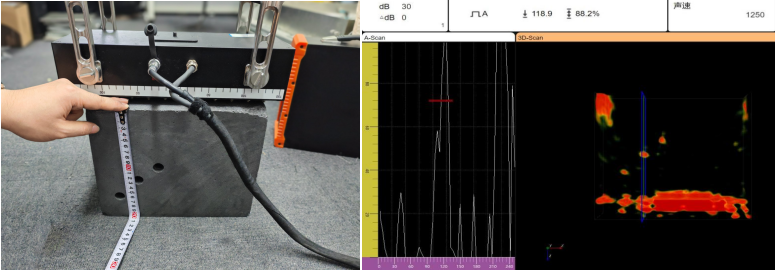
Void Defect Identification — Three φ18 mm Transverse Holes at Different Depths in a 200 mm Thick Specimen
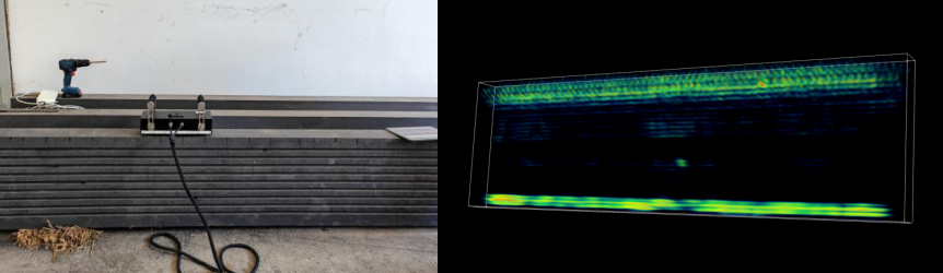
Edge Stitching Detection — Simultaneous Identification of φ13 mm Drilled Holes at 60 mm / 300 mm Depth
3D imaging intuitively presents the internal void defects of a 200 mm thick carbon-based composite specimen; three φ18 mm transverse holes at different depths are precisely identified and quantitatively located. Grid-based 3D image stitching scanning forms a full-view 3D MAP, enabling simultaneous identification of the φ13 mm drilled holes at depths of 60 mm and 300 mm.
Case 6 | Bridge Box Girder Specimen Inspection
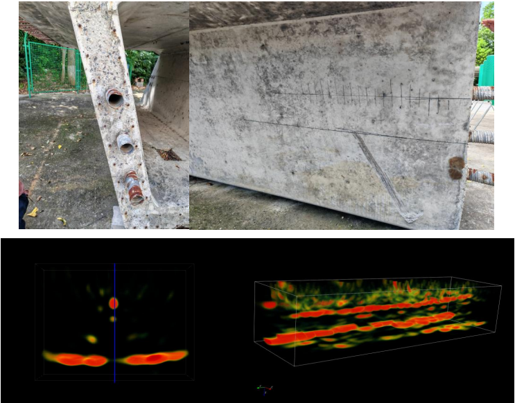
Box Girder Inspection & Stitching Imaging — φ50 mm Corrugated Duct Clearly Visible
On-site inspection detects a φ50 mm hollow corrugated duct and φ8 mm rebars inside the box girder web, with the duct outline appearing clear and complete in the stitching image.

