1. Overview
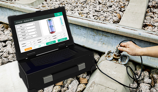
This system is a set of train wheel axle detection system customized and developed by our cooperation unit for a vehicle factory of CRRC. With the ultrasonic phased array technology, it realizes the full coverage detection of the axle unloading groove, wheel seat and gearbox seat, etc. In order to meet the needs of on-site use, this system is designed as a simple and movable semi-automatic detection system, which can move the flaw detection frame to the position of the wheel set for flaw detection. The main part of the system consists of mechanics, ultrasonic phased array instrument, host computer and software. The description of each part is showed as below:
2. Mechanics
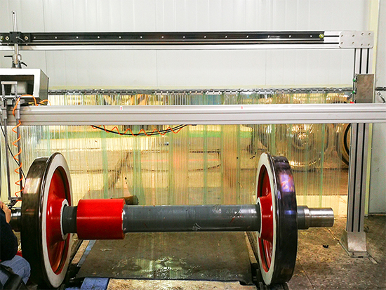
The mechanical part is composed of mobile gantry, probe holder and tool trolley. The gantry is designed to be movable and equipped with four wheels, which can be moved to the designated position and locked. The probe holder is installed on the gantry, which can move along the horizontal and vertical directions, with the elastic coupling mechanism and coupling liquid (water) spray function, to ensure the coupling between the probe and the shaft journal. The probe holder is also installed with a rotary encoder to obtain the circumferential position of the probe scanning. The tool trolley is used to carry the control box, water tank, host computer and phased array instrument, and can move with the gantry.
3. Ultrasonic phased array instrument
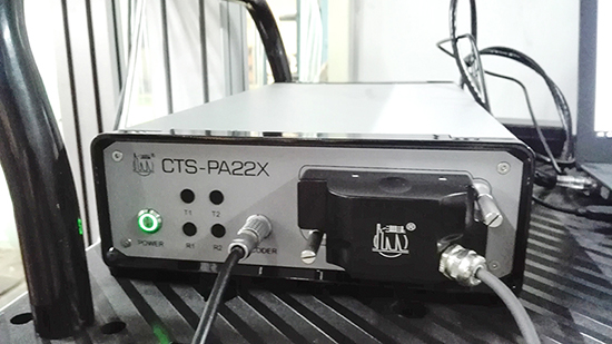
The phased array instrument part uses a CTS-PA22X instrument, which is configured with 32:128 channel, and does not equip with conventional channel. Connect a 32 element linear probe, the element pitch is 1.0mm, the wedge angle is 55 degrees, the wedge coupling surface has radian, which is consistent with the shaft journal radian. The CTS-PA22X has two encoder interfaces, one of which is connected with the encoder on the probe holder to obtain the circumferential position of the probe during scanning and transmit it to the host computer software.
4. Host computer & software
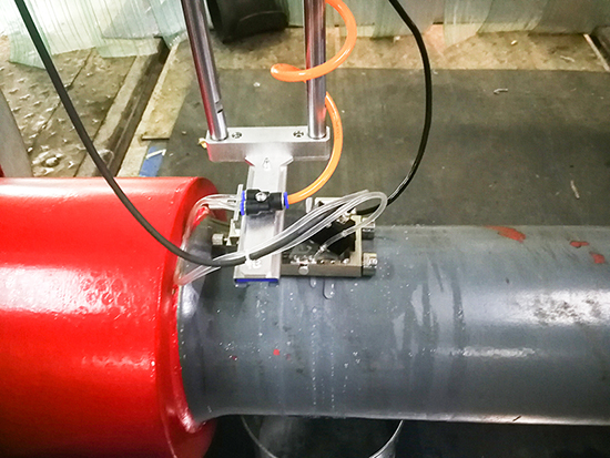
According to the needs of site work, the host computer can be notebook computer, desktop computer or industrial computer. For convenience, this system uses an ASUS notebook computer equipped with Gigabit network card, i7 CPU, 4G memory and 1t hard disk. Axle flaw detection software is developed by C + +, and data communication is carried out between the network socket and the CTS-PA22X instrument. The main interface of the software is divided into four functions: Fan scan display, A-wave display, C-scan display and parameter adjustment.
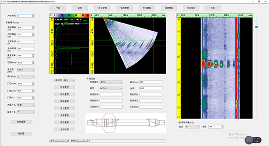
The software code refers to the PA22X-DEMO source code provided by the CTS-PA22X. The fan scan image directly maps the image data sent by the CTS-PA22X, and the A-type wave is directly drawn according to the received A-type data. C-scan needs to be slightly processed, and the corresponding depth data of S-scan is taken for projection, and then the corresponding position of C-scan image is drawn according to the reading of the circumferential encoder embedded in the data package. The parameter adjustment function is also simple. Format the input parameter into a command string and send it to the CTS-PA22X. Because the CTS-PA22X has completed the functions of S-scan, A-wave, law calculation, etc, which greatly reduces the workload of software development. The development and debugging of the entire wheel phased array flaw detection software took only one and a half months.
5. Summary
This system has realized the phased array full coverage detection of the axle unloading groove, wheel seat, gearbox seat and other parts. Simple operation, strong mobility, convenient debugging, stable performance & easy maintenance, it has been highly recognized by users. At present, it has been accepted and put into use in a factory of CRRC.


